Index
Spray cooling
Spray cooling is a continuous congealing process that produces granules by atomizing a molten liquid material into a cold gas stream and rapidly cooling and solidifying the atomized droplets. The process is generally called spray cooling, but since granulation is performed by cooling and solidifying a heated molten liquid material, it is also called spray cooling granulation, spray cooling solidification, and spray congealing.
Spray cooling utilizes technologies derived from spray drying. A liquid material is atomized into a process where a continuous cold gas stream flows. The atomized droplets have an increased specific surface area and are solidified in seconds. The solidified granules are spherical in shape and has excellent fluidity with a sharp particle size distribution. Unlike spray drying, there is no droplet shrinkage due to evaporation, resulting in larger granules. Spray cooled powder is also called beads, prills, etc., and can generally be granulated in the range of several tens of micrometers to several millimeters. By using molten liquid as a membrane material and mixing core materials, microencapsulation can easily be performed. Encapsulation efficiency is high (90–100%) when compared to other microencapsulation processes including spray drying. Cooling gas used in the process is mainly atmospheric air. A closed-cycle system with the use of inert gas (e.g. nitrogen) as a process gas is selected if a liquid material contains flammable ingredients or is sensitive to oxidation. Spray cooling is a simple and continuous process that can potentially eliminate downstream processes such as grinding, classification, and granulation.
Characteristics of spray cooling
- Production process can be simplified because powder can be obtained directly from liquid.
- Spray cooled granules are spherical in shape, have excellent fluidity and a sharp PSD.
- Precise particle control is possible with a variety of atomization systems.
- Continuous process: easy to scale up and suitable for mass production.
- High-level microencapsulation is achievable.
Applications
Waxes, Saturated fatty acids, Stearic acid, Palmitic acid, Lauric acid, Myristic acid, Fatty acid amide, Sebacic acid, Phospholipids, Palm oil emulsifying wax, Sodium stearoyl lactate, Essential oils, Paraffins, Terpenes, Steroids, Carotenoids, Fish oil, Omega 3 fatty acids, Omega 6 fatty acids, Glycerin, Monoglycerides, Diglycerides, Triglycerides, Polyoxylglycerides, Poloxamers, Polyethylene glycol (PEG), Higher alcohols, Phthalic anhydride, Maleic anhydride, Dimethyl terephthalate, Microcapsules, Polymers, Petroleum resins, Phenolic resins, PVC stabilizers, Latex, Elastomers, Synthetic rubber, Urea, Inorganic melts, Organic melts
Process overview
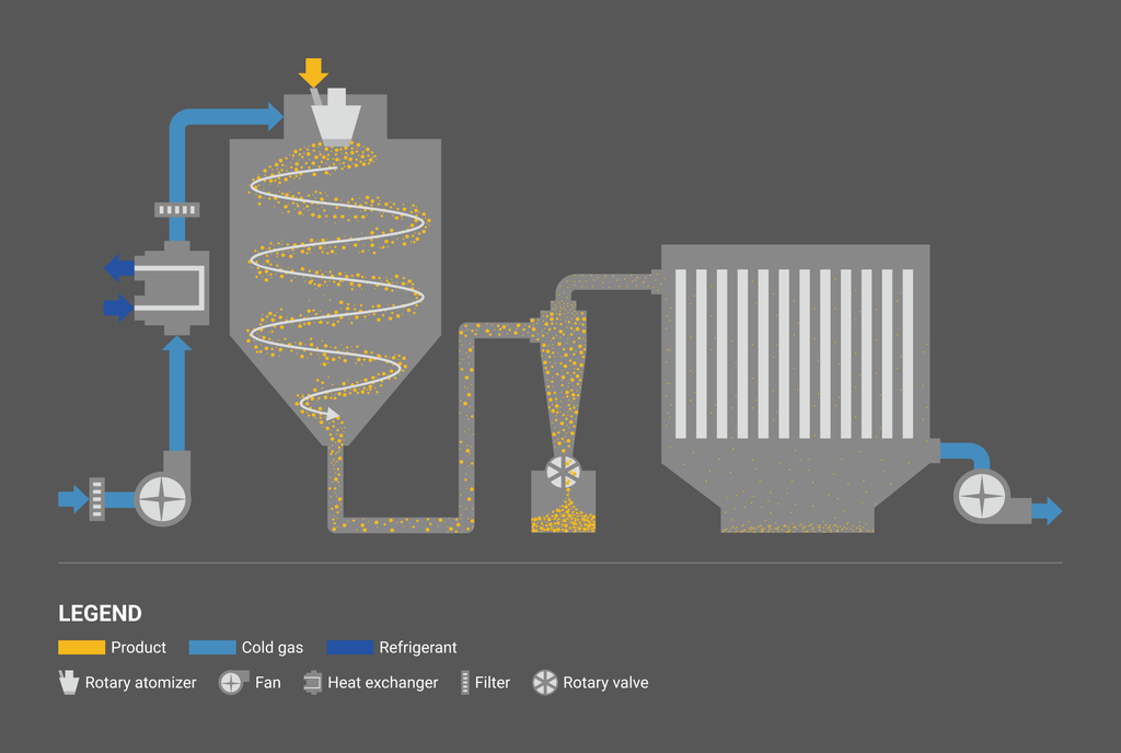
Spray cooling process consists of three steps: liquid atomization, solidification of droplets, and separation and recovery of solidified powder.
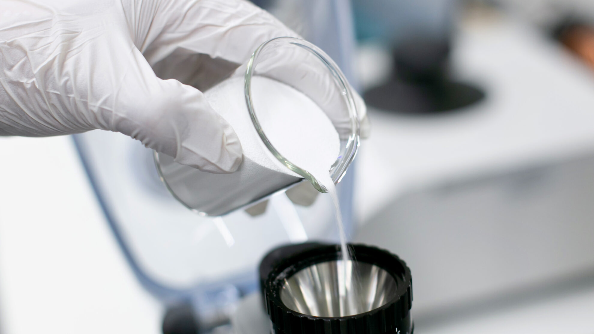
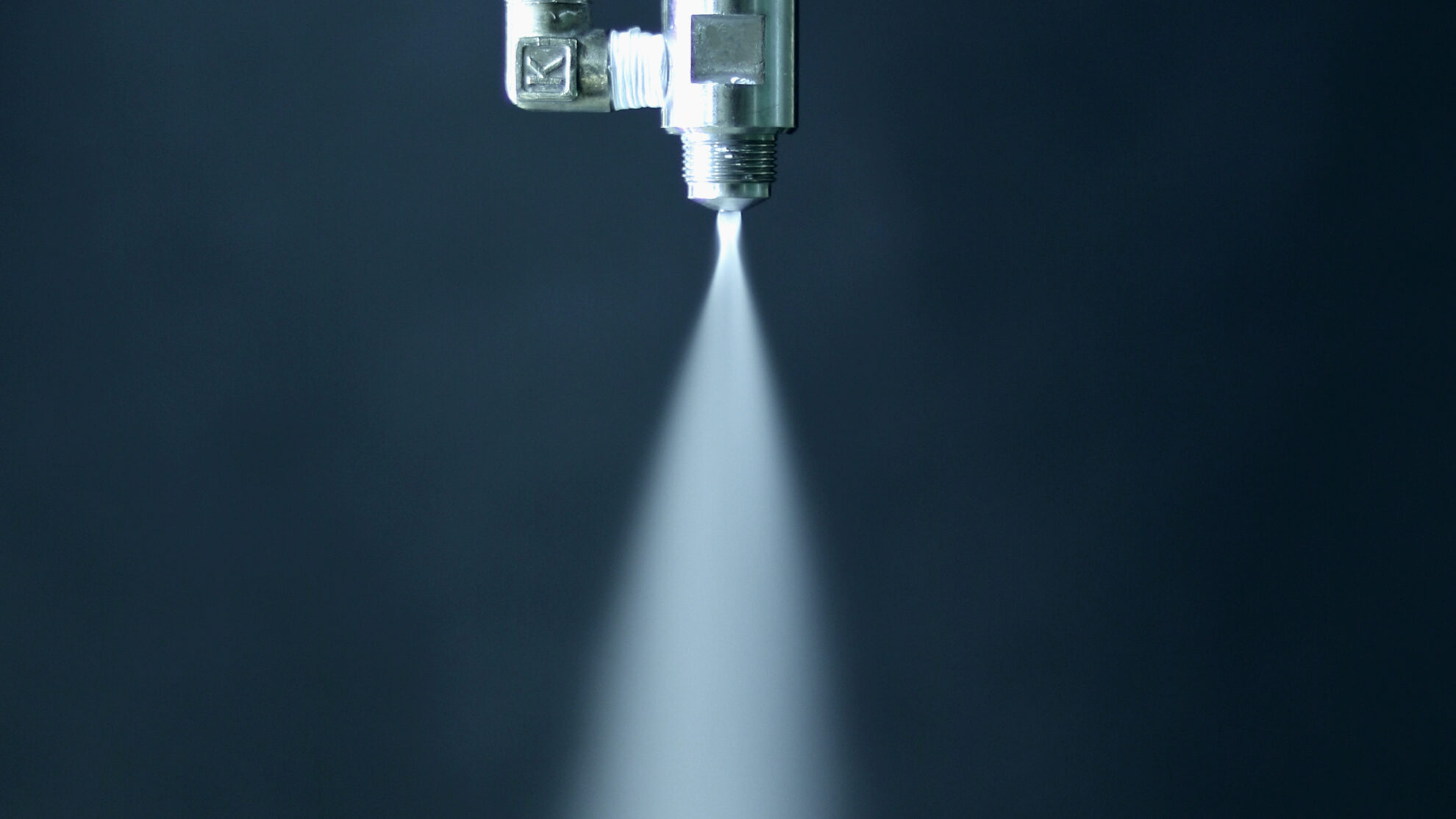
Liquid atomization
A molten liquid is sprayed by an atomization system into a cooling process where a continuous low-temperature gas stream flows. The droplets sprayed by an atomization system have an increased specific surface area, and the droplets are cooled and solidified in a short period of time, ranging from a few seconds to several tens of seconds. The particle size and the shape of solidified powders are strongly influenced by the shape of droplets during atomization. Therefore, the first step for designing a spray cooling process is to determine the right atomization system and operating conditions that can produce the desired granule quality (Click here to learn more about Liquid Atomization).
A liquid supplied to an atomization system is destabilized by the impact of internal and external energy given, causing it to flow, deform, and breakup. A supplied liquid becomes more unstable due to turbulence in the liquid as the flow rate increases. Furthermore, the addition of external forces such as air causes fragmentation, forming ligaments and droplets. External forces mainly include shear forces and forces acting on the interface between the liquid and the outside air (surface tension and negative pressure due to airflow). A state in which most of the liquid flow becomes droplets is called an atomization flow. Droplets repeat re-splitting during liquid disintegration process, becoming finer and forming an atomization flow. In theory, re-splitting is repeated until the droplet’s surface tension balances out the force caused by the irregular turbulence of the external air.
The main factors in liquid atomization are the physical properties of a liquid and a gas and the energy added externally.
Physical properties of a liquid and a gas
Density ( ρ ), Viscosity ( μ ), Surface tension ( σ ), Specific heat ( c ), Thermal conductivity ( λ ), Temperature diffusivity ( α ), etc.
Energy added externally
Liquid flow rate ( ν ), Atomization pressure ( p ), Atomization speed ( ν ), Rotational speed ( N ), Temperature ( T ), etc.
Energy added externally works to make a liquid unstable, while the liquid works to resist deformation and return to its original stable state. The stability of a liquid in an atomization flow is derived from the dimensionless numbers of the liquid’s inertial, viscous, and surface tension forces. Typical dimensionless numbers include the Reynolds number ( Re ), Weber number ( We ), jet number ( Je ), stability number ( St ) derived from Reynolds number and Weber number, and Ohnesorge number ( Oh ).
Atomization properties are influenced not only by an atomization system but also by physical properties of a liquid material and process conditions of a spray cooler. In terms of physical properties of a liquid, density, viscosity, pH, dispersion, and properties of primary particles in the case of a slurry or a suspension are affected. In the process conditions, the design of a spray cooler, process gas temperature, process gas flow, internal pressure, etc. are the properties to be affected. Therefore, it is important to consider the characteristics of the liquid material and manufacturing process and determine the atomization system and atomization conditions that will yield the desired granule quality.
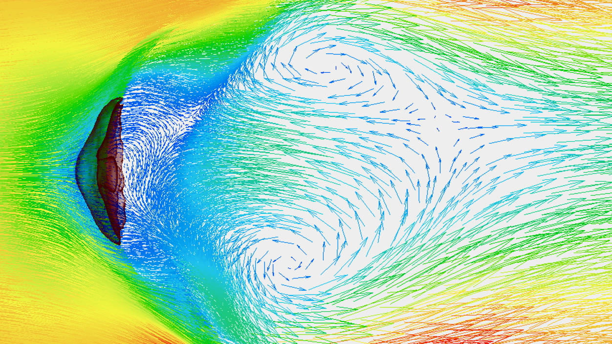
Solidification of droplets
Atomized molten droplets come into contact with a process cold air that is continuously supplied into a spray cooler process, and solidify while droplets float in the process gas flow. Solidification speed of droplets generally ranges from several seconds to several tens of seconds. The heat transfer coefficient of droplets is much larger during the acceleration phase immediately after atomization compared to the free fall phase after reaching the terminal velocity. The heat transfer coefficient in the free-fall phase can be estimated by Ranz and Marshall correlations derived from Nusselt number ( Nu ), Prandtl number ( Pr ) and Reynolds number ( Re ) as the concentration of droplets per unit space becomes diluted. However, actual behavior varies due to agglomeration and interference of droplets during fall-down time, physical properties of a liquid material, and process conditions.
Solidification speed and properties also depend on the physical properties of the liquid material and process conditions. In the case of fatty acids such as stearic acid, atomized droplets dissipate heat through continuous contact with a low-temperature air stream, and the temperature of the droplets decreases during the material pre-cooling period, passes through supercooling due to freezing point depression, and then transitions to the solidification period. During the solidification period, the solidification of droplets releases the latent heat of solidification. The solidified granules enter a solid cooling period where the temperature of the granules decreases. In spray cooling, the amount of heat and time required to cool and solidify a liquid material are calculated from the physical properties of the material and the process conditions such as process gas temperature and gas flow volume. The material pre-cooling period is calculated from the droplet temperature during atomization, the heat transfer coefficient of the droplet surface, the constant pressure specific heat of the liquid material, and the density of the liquid phase. The solidification speed during the solidification period is derived from the droplet diameter, the freezing point of the liquid material, the latent heat of solidification, the heat transfer coefficient of the droplet surface, the density of the solid phase, the thermal conductivity of the solid phase, etc. The solid cooling period is calculated from the temperature of the solid granules, the heat transfer coefficient of the solid surface, the constant pressure specific heat of the solid, and the density of the solid phase.
Separation & recovery of solidified powder
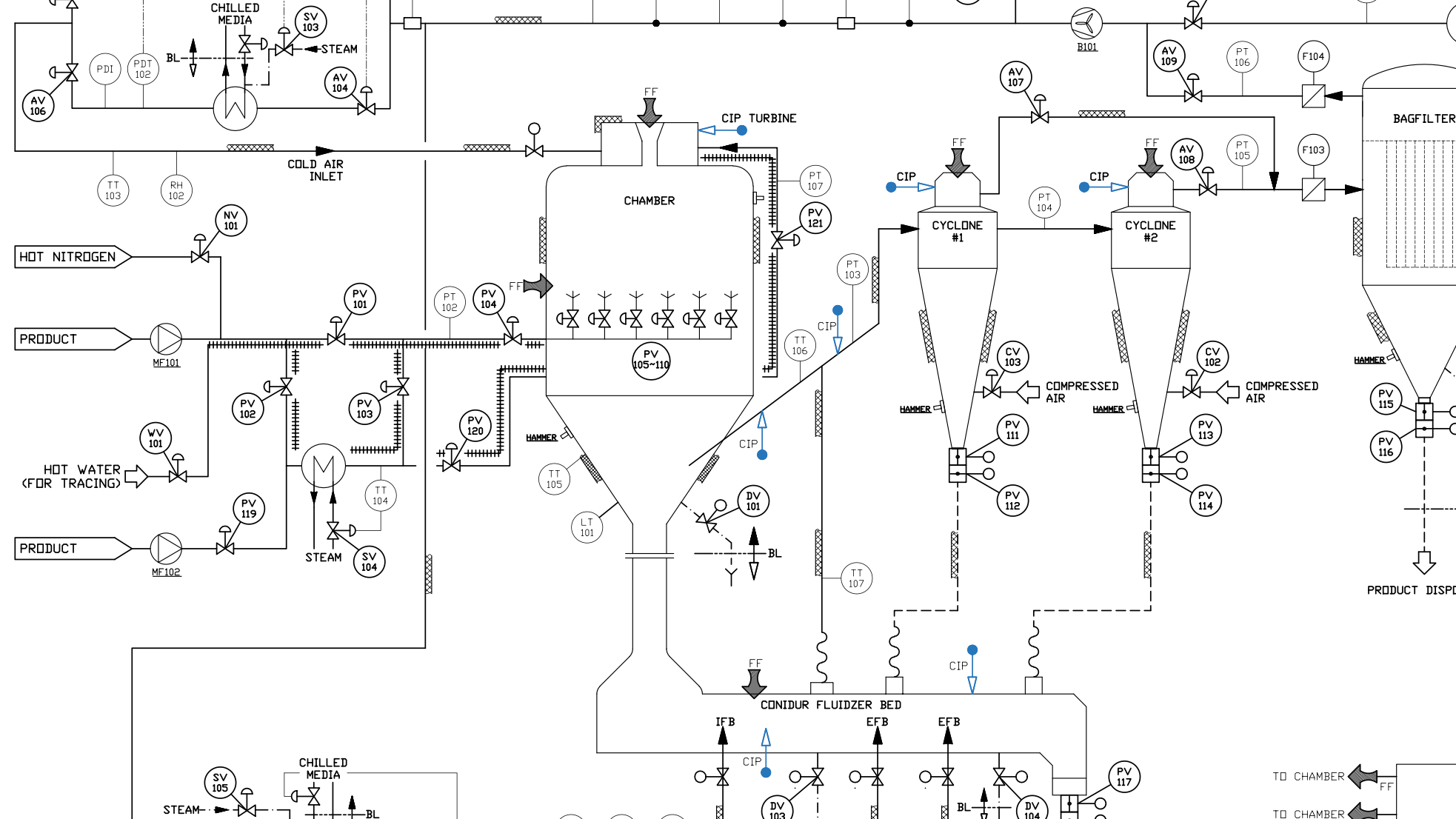
Solidified powder falls in a swirling gas flow inside a cooling chamber. Atomized droplets are solidified before contacting the inner walls of the cooling chamber. A properly designed spray cooler has an effective volume proportional to the distance the product must fall to solidify, minimizing the amount of unsolidified product stuck to the inner walls. Separation and recovery of solidified powder includes a product recovery mechanism that collects the powder as a product and a final dust removal system that prevents fine particles remaining in the process gas from being discharged outside the process after product recovery.
Product recovery mechanisms include direct recovery at the bottom of the cooling chamber and recovery using a cyclone. When collecting granules directly from the cooling chamber, the cooling chamber becomes taller because the effective chamber volume is required to accommodate the solidification period when granules fall down to the bottom of the chamber. Therefore, as the volume of the cooling chamber is limited to the amount of time and distance required for solidification, a powder conveying line equipped with cooling function may be incorporated at the bottom of the cooling chamber. Powder conveying lines include vibration sieving and fluidized bed, and the cooling time is controlled by adjusting the amount of cold air supplied. Granules that have passed through the cooling chamber are collected by a cyclone and sent to the powder conveying line. In some cases, all products are collected at once using a cyclone system. The products collected in bulk by the main cyclone system in the process are sent to the pneumatic conveying line, where they are cooled during transport and then collected by the final cyclone. A final dust removal system primarily uses a bag filter unit. Powder recovered by a dedusting system may be of inferior quality or may be treated as waste and therefore treated as a loss. When removing dust using a bag filter unit, the collected powder may be reused when handling a single variety. When handling a wide variety of products, a cleaning process is required to prevent cross-contamination. The equipment and operation costs involved in cleaning bag filters are high, so this kind of processes is not generally used except for some high value-added products.
In order to increase the productivity of spray coolers, it is important to select an appropriate powder recovery system to maximize collection efficiency. In addition, when selecting a final dust removal system, it is necessary to consider not only environmental and sanitary aspects, but also investment costs and operating costs.
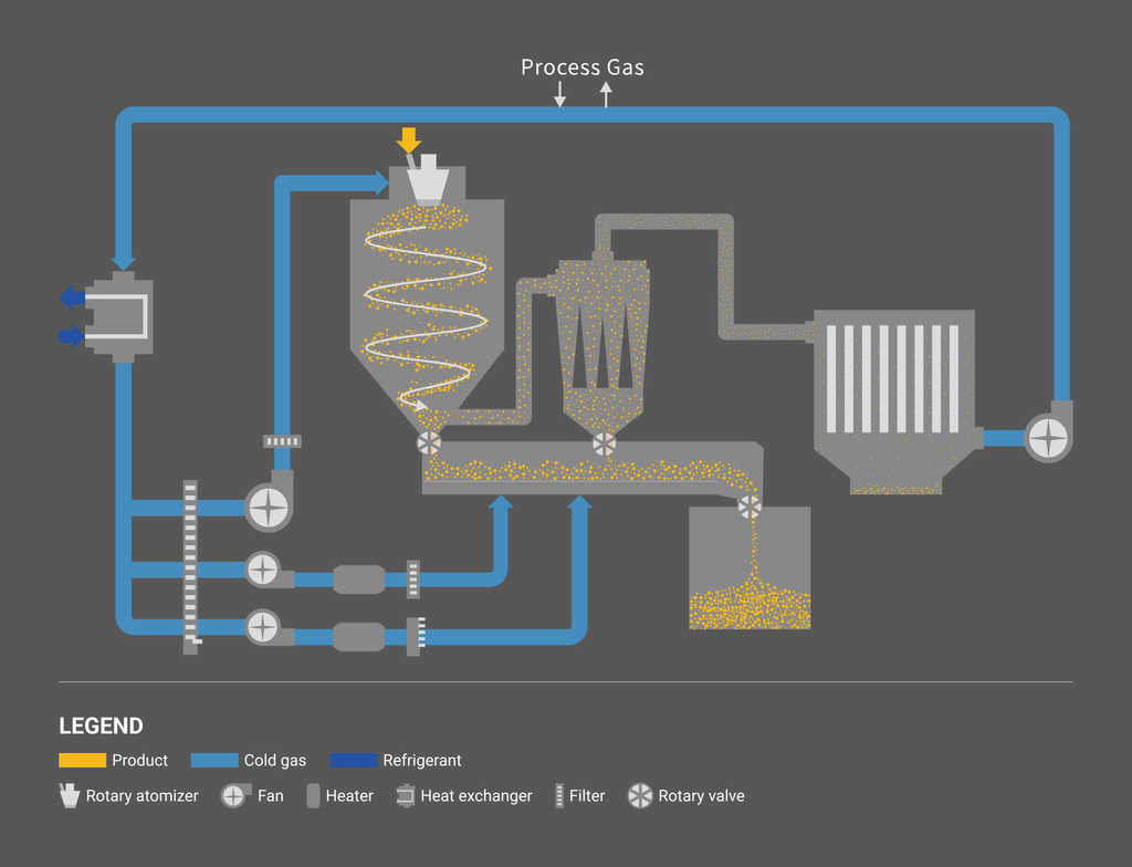
Process flows
Open-cycle system
Closed-cycle system
Spray cooling processes generally consist of the following functions:
Liquid supply system
A molten liquid is supplied by a pump from a material tank to an atomization system installed in a cooling chamber. The temperature of the liquid pipe line is maintained constant to prevent the liquid temperature from dropping and causing the raw material to solidify and become clogged. Temperature is usually maintained by heated and insulated jacketed piping. The heating medium generally uses hot water, steam, electricity, etc. In general, liquid supply systems are fully automated.
Process gas supply system
Process gas is supplied using two main fans integrated at the inlet and outlet of the spray cooling process. The system incorporates filtering systems such as pre-filters, high-performance filters, and HEPA filters to eliminate contamination and supplies clean gas that is cooled by a cooling source supply system. By adjusting the process gas volume of the inlet and outlet fans, the process internal pressure is controlled to stabilize the physical properties of the solidified granules. The amount of process gas supplied is optimally calculated based on mass and heat balances. The calculation formula also takes into account ambient conditions such as temperature and humidity including seasonal fluctuation factors at the location where the process is installed, and dehumidification and precooling systems may be added as necessary.
Cooling source supply system
A cooling source supply system plays the role of cooling a spray cooler process gas. An optimal cooling source supply system is selected from the utilities available at the installation site, taking into consideration operating costs, stability, and efficiency. In general, systems are combined with a chiller unit, cold water, refrigerant, etc. If precise temperature controls are required, a heater can be incorporated in the latter stage and automatic control can be performed using a feedback control system.
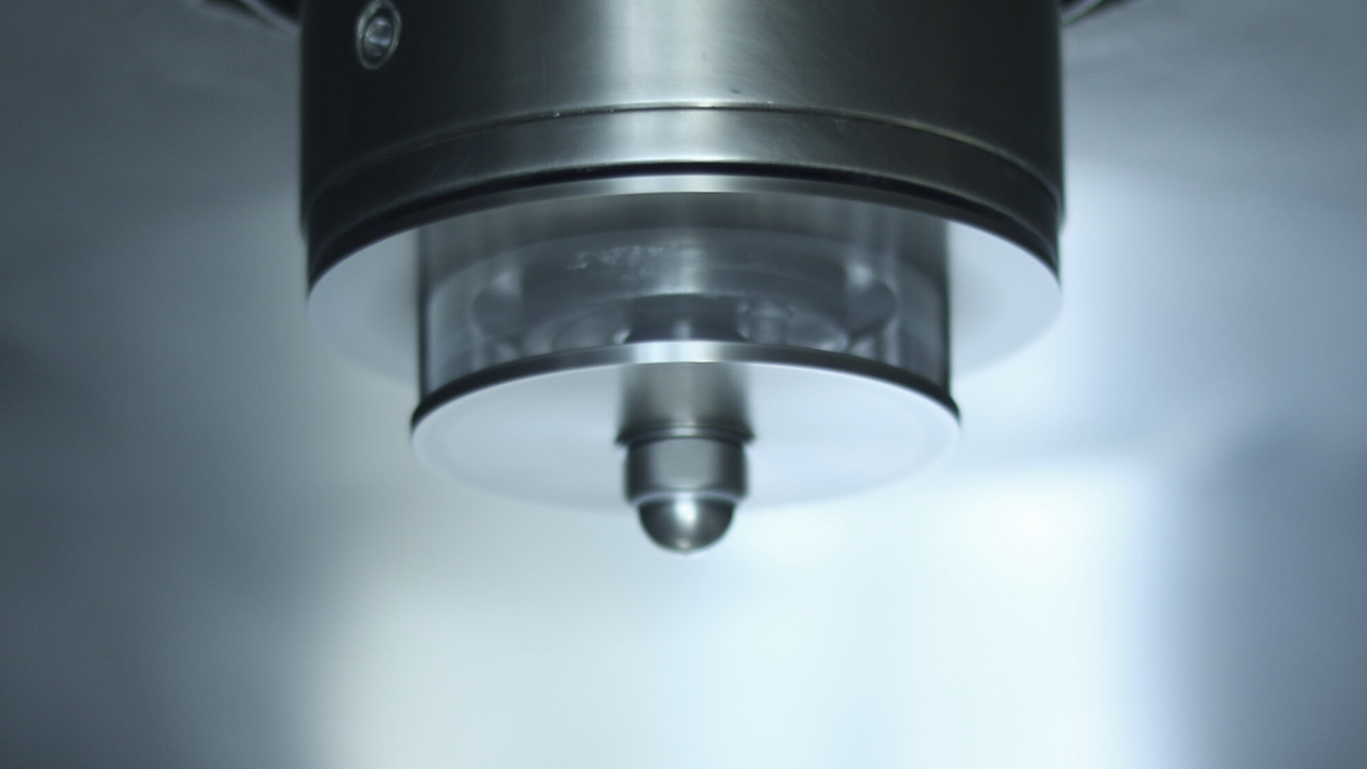
Liquid atomization system
A liquid supplied from a liquid supply system is atomized into a cooling chamber by an atomization system. A variety of liquid atomization systems are available such as rotary atomizers, single-fluid nozzles (pressure nozzles), two-fluid nozzles, and ultrasonic nozzles, depending on the required powder properties (Click here to learn more about Liquid Atomization). Our patented technology, Auto PSD Control Atomizer System, measures the particle size of the powder flowing through the process in real time, and the rotational speed of the rotary atomizer is automatically adjusted by our original patented algorithm. Since the particle size is automatically controlled as a set value without fixing the rotational speed, the system can precisely keep the set PSD during the operation. In addition, our patented Coanda Disc can increase the droplet fall distance and it allows for the efficient use of chamber space. By applying the Coanda effect which is the effect that fluid is attracted to a nearby wall, the atomized droplets are directed downward and the droplets fall distance becomes longer so that it is effective to increase production efficiency. Our state-of-the-art two-fluid nozzle has the same level of performance as multi-fluid nozzles such as four-fluid nozzles, and can atomize to single microns while significantly reducing compressed gas consumption.
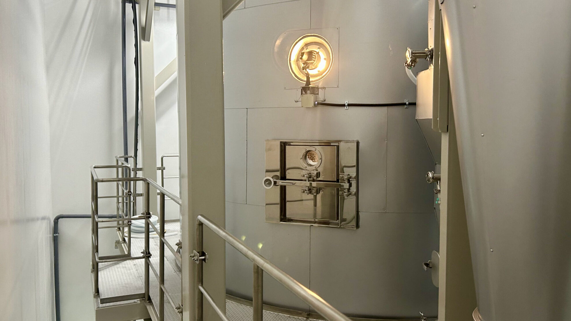
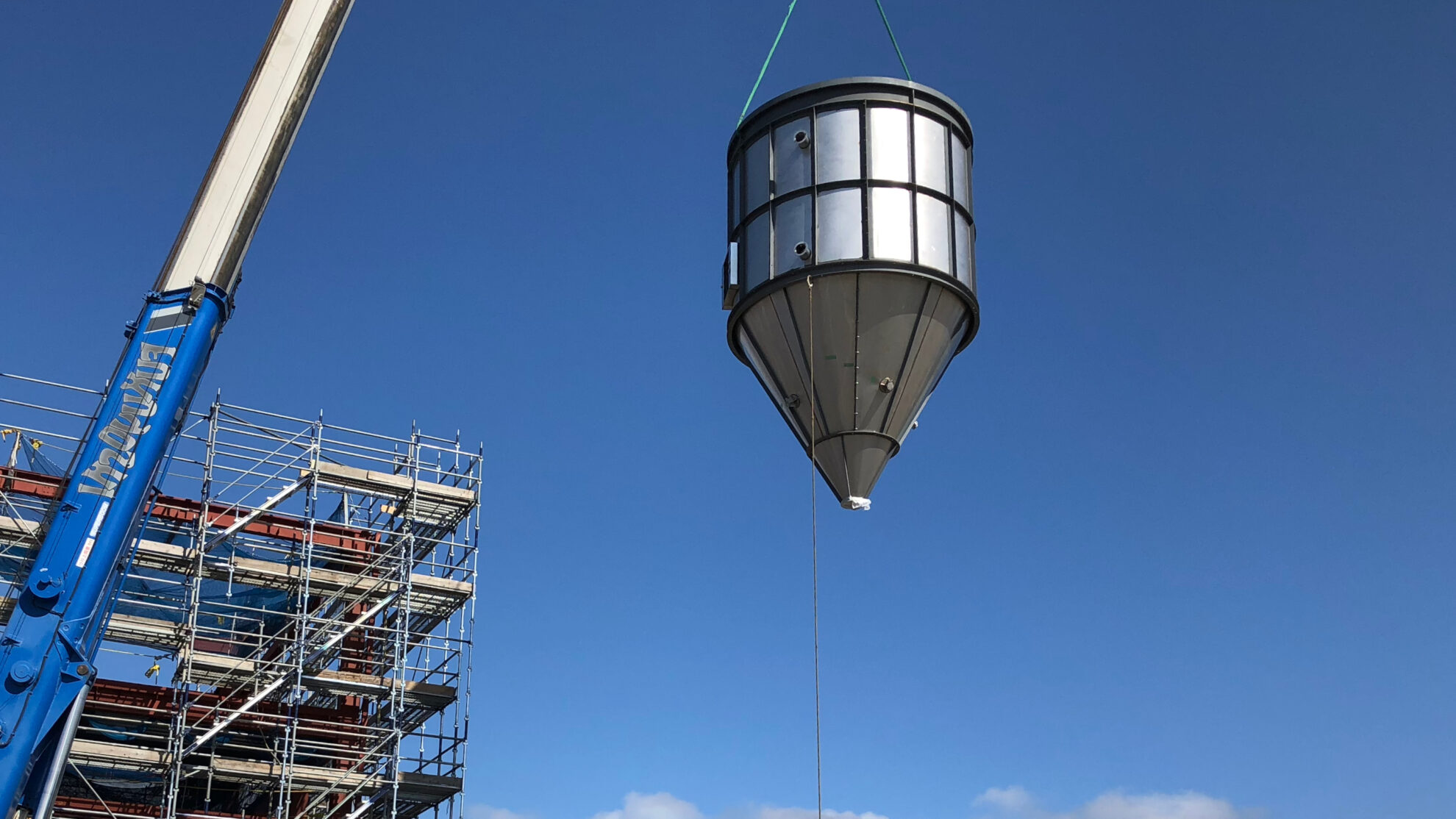
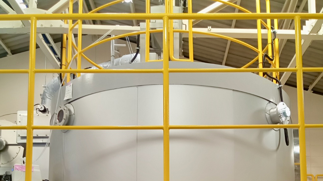
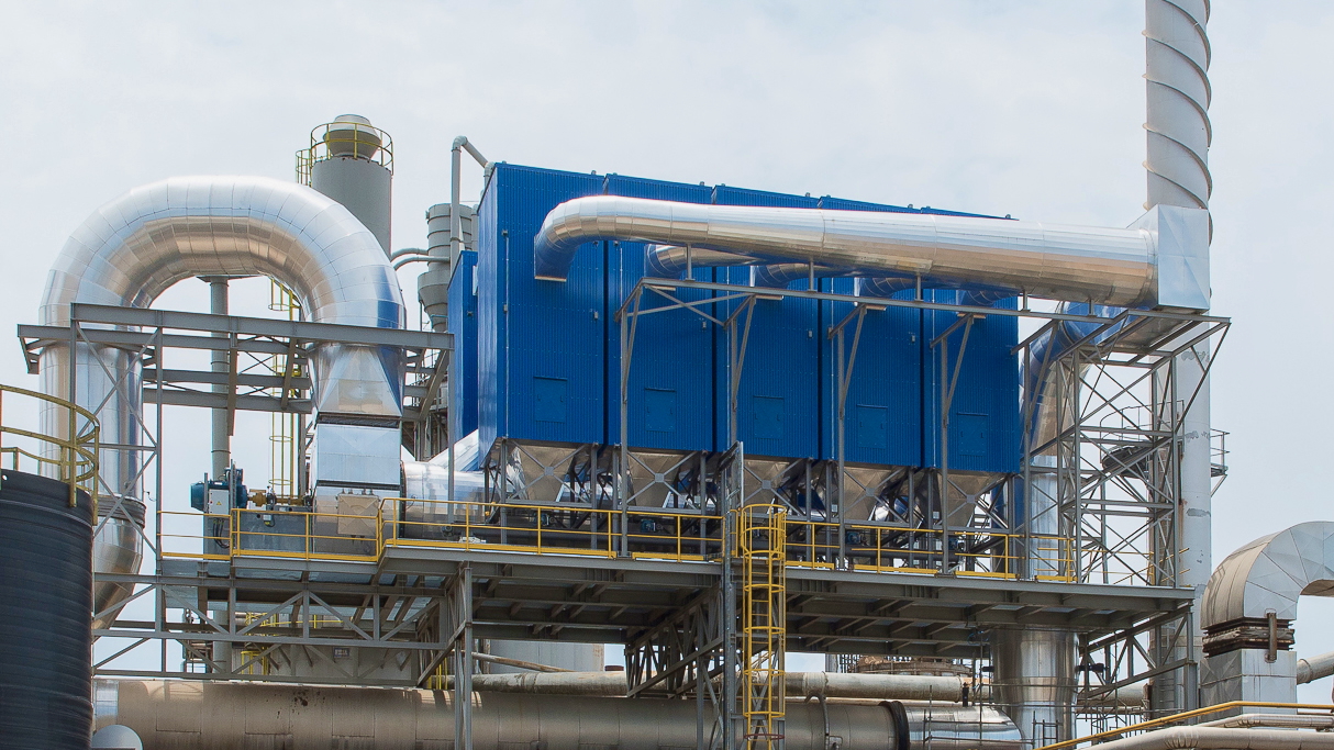
Cooling chamber
Molten droplets atomized into a cooling chamber comes into contact with a cold gas stream that is continuously supplied into the spray cooling process and solidify in seconds. A process gas is supplied to an air disperser installed at the top of the cooling chamber. The process gas is rectified by an air disperser, creating an appropriate swirling airflow to efficiently solidify the atomized droplets. The size, shape and effective volume of the cooling chamber are determined based on the target properties of the powder and the required operating conditions. Specifically, in addition to the calculation of the mass balance and heat balance, the residence time and distance of the granules are calculated and determined based on the characteristics of the selected atomization system and the physical properties of the atomized droplets. Solidification speed of droplets generally ranges from several seconds to several tens of seconds. A properly designed spray cooler minimizes the adhesion of unsolidified product on inner walls by securing enough residence time and distance to be solidified for atomized droplets. If the powder residence time is too short, it will cause unsolidified material to stick in the process.
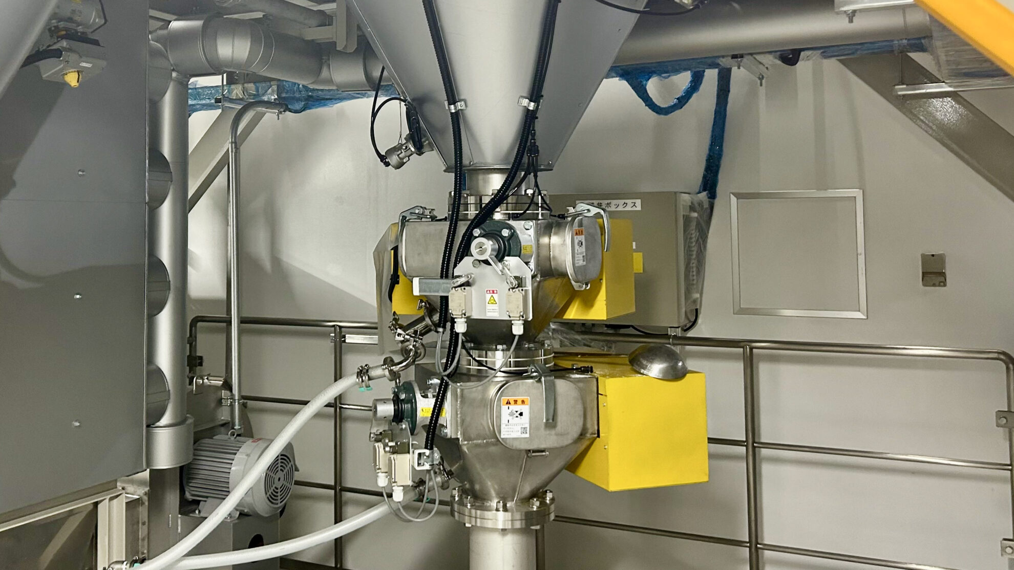
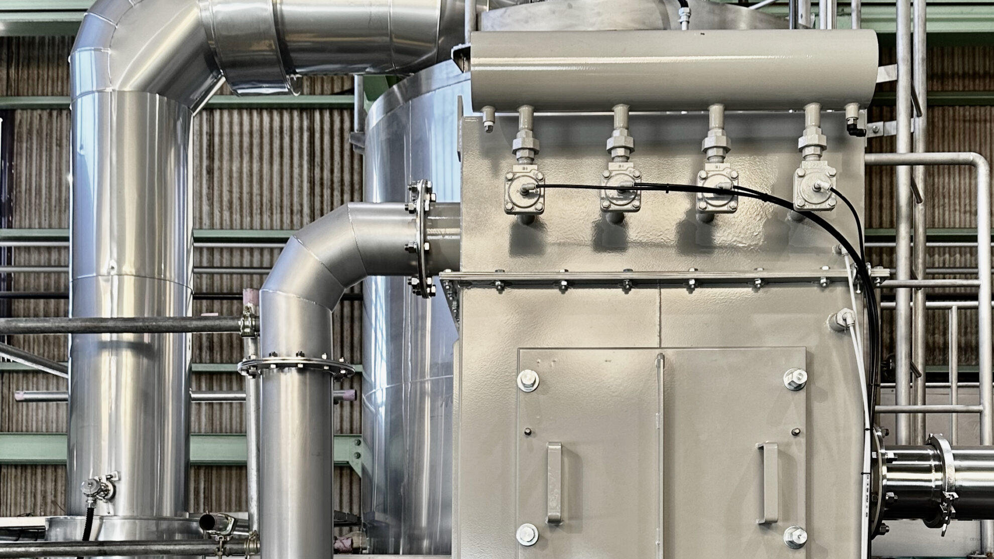
Product separation & recovery system
In the case that products are collected at two points: the bottom of the cooling chamber and a cyclone, spherical granules with good fluidity can be collected at the bottom of the cooling chamber, and fine particles are obtained at a cyclone. When product collection is performed at a cyclone, an optimal cyclone system is designed according to the production scale and operating conditions of the spray cooler. Through our partnership with Portugal’s ACS, we may also offer high-efficiency cyclones that incorporate the PACyc (particle aggregation in cyclones) model into the design optimization simulations. In addition to improving product yield, ACS’s high-efficiency cyclones can eliminate the need for final dust removal systems such as bag filters in many cases. Adopting a high-efficiency cyclone not only improves product recovery rate (reduces raw material loss), but also reduces equipment investment costs by omitting a bag filter unit. In addition, a powder conveying line equipped with cooling function may also be incorporated at the bottom of the cooling chamber. Powder conveying lines include vibration sieving and fluidized bed, and the cooling time is controlled by adjusting the amount of cold air supplied. Particles that have passed through the cooling chamber are collected by a cyclone and sent to the powder conveying line. Final dust removal systems are selected from bag filter units, high-efficiency cyclones, etc., taking into consideration environmental compatibility, hygiene, capital investment, and operating costs.
Cleaning system
Spray coolers need to be cleaned regularly in food and pharmaceutical industries or when manufacturing multiple products in a single process. A small spray cooler for R&D needs to be designed to easily disassemble and have excellent sanitary properties. In small-scale spray coolers, budget constraints may preclude automated cleaning systems. On the other hand, research institutes that continuously conduct high-mix, low-volume productions, and multi-condition trials may adopt automatic cleaning systems for their efficient operations. For medium-sized pilot spray coolers and mass production plants, it is necessary to adopt an appropriate cleaning system, taking into consideration the installation cost and operation cost of the cleaning system, as well as the required quality level. When introducing a cleaning-in-place (CIP) system, the design process should include the cleaning systems and controls in advance in the overall process. We take into account the required process specifications and raw material characteristics to design the optimal cleaning systems and controls. A typical CIP system includes water, acid, and alkali storage tanks, buffer tanks, liquid pumps, cleaning nozzles, and various sensors. A general sequence control of cleaning processes is rough cleaning with hot water, alkaline cleaning, acid cleaning, hot water rinsing, final rinse, and drying. A properly designed cleaning system is required to avoid wasting operational costs such as cleaning chemicals and operation time. In order to carry out CIP effectively, comprehensive engineering is required, such as formulating chemicals and physicochemical cleaning processes according to the characteristics of raw material contamination, and selecting cleaning equipment suitable for the structure of the spray cooling process. Depending on the unique characteristics of the raw materials and the structure of the production process, it may also be possible to construct a cleaning process that is more hygienic and stable than a fully automatic CIP system by partially adopting COP and separating the part from automatic cleaning of the entire process (Semi-CIP system).
Trials, contract processing & analytical measurements
We not only provide powder processing trials for spray drying, spray cooling, and freeze granulation, but also services that include pre- and post-powder processing, such as wet pulverizing, mixing, molding, sintering and freeze-drying. We operate a total of three locations: two Powder Technical Centers in Japan and ASEAN Powder Technical Center in Thailand under the partnership with T.S.K. Engineering. Our brand new Powder Technical Center 2 (PTC2), which was newly established in 2023, has one of the largest collections of analytical measurement equipment in Japan. We provide one-stop support for powder processing and analytical measurements (Powder Trials & Analytical Measurements / Contract Powder Processing).
Related information